When ordering custom aluminum finned tubes for a heat exchanger, providing only the tube diameter, material, or overall length is rarely enough. A complete specification must connect the heat exchanger operating conditions, base tube dimensions, fin geometry, finning method, tolerances, material requirements, and quality standards.
For heat exchanger manufacturers, engineering companies, and procurement teams, a well-prepared specification reduces quotation errors, prevents dimensional mismatches, and helps an aluminum finned tube manufacturer determine the appropriate manufacturing process.
This guide explains what information should be included in a custom aluminum finned tube specification and how to prepare a technically complete RFQ.
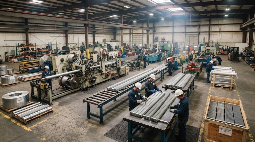
Start with the Heat Exchanger Operating Requirements
Before specifying tube and fin dimensions, define the operating conditions of the heat exchanger. These conditions determine which aluminum alloy, tube dimensions, fin configuration, and manufacturing method are suitable.
1. Heat Duty
The required heat transfer duty is one of the most important inputs for a custom finned tube project. Provide the required heating or cooling capacity, preferably in kW, BTU/h, kcal/h, or another clearly defined unit. The manufacturer may also need the required inlet and outlet temperatures for both sides of the heat exchanger. Without this information, it is difficult to evaluate whether the proposed finned tube provides sufficient effective heat transfer area.
For example, a tube designed for a small HVAC coil and one intended for an industrial air cooler may have very different fin density, tube dimensions, and thermal requirements even if both are made from aluminum.
2. Tube-Side and Fin-Side Fluids
Specify what flows through the tube and what contacts the external fin surface. Typical tube-side fluids include:
- Water
- Refrigerant
- Oil
- Glycol solution
- Process fluids
- Industrial gases
The fin side may be exposed to ambient air, forced air, combustion gases, or another process gas. The fluid type matters because it affects corrosion resistance, pressure requirements, heat transfer conditions, and material compatibility.
3. Operating Temperature and Pressure
A complete finned tube RFQ should include:
- Normal operating temperature
- Minimum and maximum operating temperature
- Design temperature
- Operating pressure
- Design pressure
- Pressure fluctuations, if applicable
Temperature and pressure should be specified separately from the target heat transfer performance. A finned tube that provides adequate heat transfer may still be unsuitable if its tube wall or fin construction cannot withstand the actual operating environment.
4. Flow Rate and Environmental Conditions
For air-side applications, provide airflow rate or air velocity when available. For tube-side applications, provide fluid flow rate and relevant fluid properties. Outdoor installations should also identify environmental conditions such as humidity, salt exposure, dust, or corrosive industrial atmospheres. These factors can influence the appropriate aluminum alloy and finned tube construction.
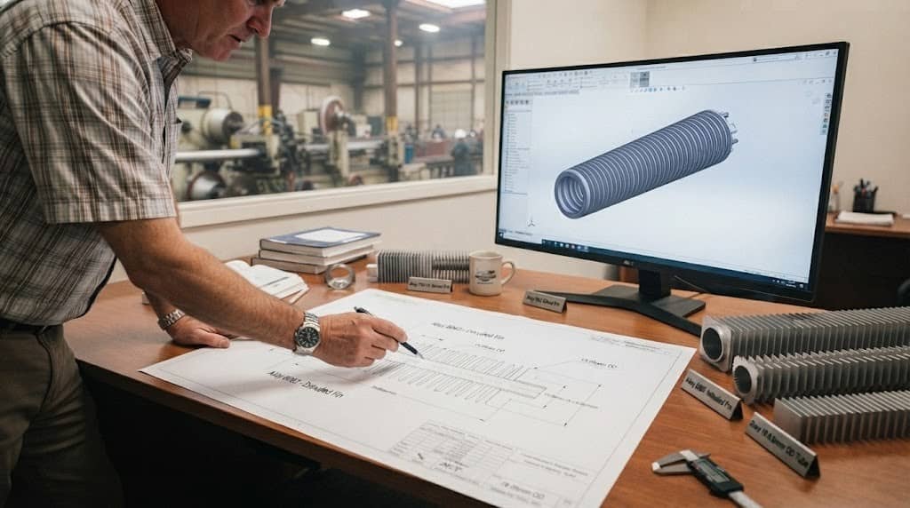
Define the Base Tube Specifications
The choice of aluminum should be based on thermal conductivity, weight, corrosion resistance, mechanical requirements, and compatibility with the intended application. For more background on material selection, see our guide to aluminum as the finned tube material.
1. Tube Material and Aluminum Alloy
The specification should clearly identify the required aluminum alloy rather than simply stating “aluminum tube.” Depending on the application, available alloys may include 1050, 1060, 1070, 1100, 5052, and 6063, among others. The appropriate alloy depends on the required combination of thermal conductivity, corrosion resistance, mechanical properties, formability, and manufacturing requirements.
For a custom aluminum finned tube, the tube alloy and fin alloy should be identified separately when different materials are used. For example:
- Tube: Aluminum 6063
- Fin: Aluminum 1100
This is much more useful to a manufacturer than simply specifying “aluminum finned tube.”
2. Tube Outside Diameter
Specify the tube outside diameter (OD) using a clearly defined measurement system. For example:
- 12 mm OD
- 16 mm OD
- 19.05 mm OD
- 25.4 mm OD
- 1 inch OD
Also identify the required dimensional tolerance if the tube will be installed into headers, manifolds, plates, or other precision components. The tube OD affects internal flow area, pressure drop, heat transfer surface, fin dimensions, and compatibility with the rest of the heat exchanger.
3. Tube Wall Thickness
Tube wall thickness should be specified according to pressure, mechanical requirements, corrosion allowance, manufacturing capability, and applicable design requirements. A thicker tube wall can increase mechanical strength, but it may also increase material consumption and affect heat transfer resistance. Therefore, wall thickness should not be selected solely according to material cost.
A good specification should distinguish between:
- Nominal wall thickness
- Minimum allowable wall thickness
- Manufacturing tolerance
For pressure-containing applications, the design engineer should confirm the required wall thickness based on the actual operating and design conditions.
4. Tube Length and Unfinned Ends
Specify both the overall tube length and the effective finned length when they are different. Also define:
- Unfinned end length
- One-end or two-end unfinned sections
- Connection areas
- Header insertion length
- Tube cutting tolerance
This information is especially important when the finned tube will be assembled into a heat exchanger core. An incorrect unfinned length can interfere with header installation even when the tube and fin dimensions themselves are correct.
Specify the Fin Geometry
When preparing a custom specification, each fin dimension should be clearly defined rather than described using general terms. Understanding the role of the major aluminum finned tube parameters can also help engineers establish appropriate dimensional requirements.
1. Fin Height
Specify the required fin height and the measurement reference. For example:
Fin height: 10 mm ± 0.2 mm
The specification should clarify whether the dimension is measured from the tube surface to the fin tip or represented as part of the overall finned diameter. Fin height influences available heat transfer area, overall tube diameter, airflow characteristics, and equipment footprint. Increasing fin height is not automatically beneficial because the optimum geometry depends on the heat exchanger’s thermal and aerodynamic requirements.
2. Fin Thickness
Specify the nominal fin thickness and tolerance. For example:
Fin thickness: 0.4 mm ± 0.03 mm
Fin thickness affects mechanical durability, material consumption, manufacturing consistency, and the ability of the fin to maintain its geometry during handling and operation. For high-density fins, dimensional consistency is particularly important because small variations can accumulate across a long tube.
3. Fin Pitch and Fin Density
Fin pitch is the distance between adjacent fins, while fin density describes how many fins are installed within a specified length. When preparing a specification, clearly state whether the requirement is expressed as:
- Fin pitch in mm
- Fins per inch (FPI)
- Fins per meter
- Another defined density convention
For example:
- Fin pitch: 2.0 mm
- Fin density: 12 FPI
Do not provide an unexplained value such as “12 fins” because the manufacturer needs to know the reference length. Fin pitch and density affect heat transfer surface area, airflow resistance, cleanability, and pressure drop. The required value should therefore be determined together with the heat exchanger’s air-side operating conditions.
4. Fin Shape and Segmentation
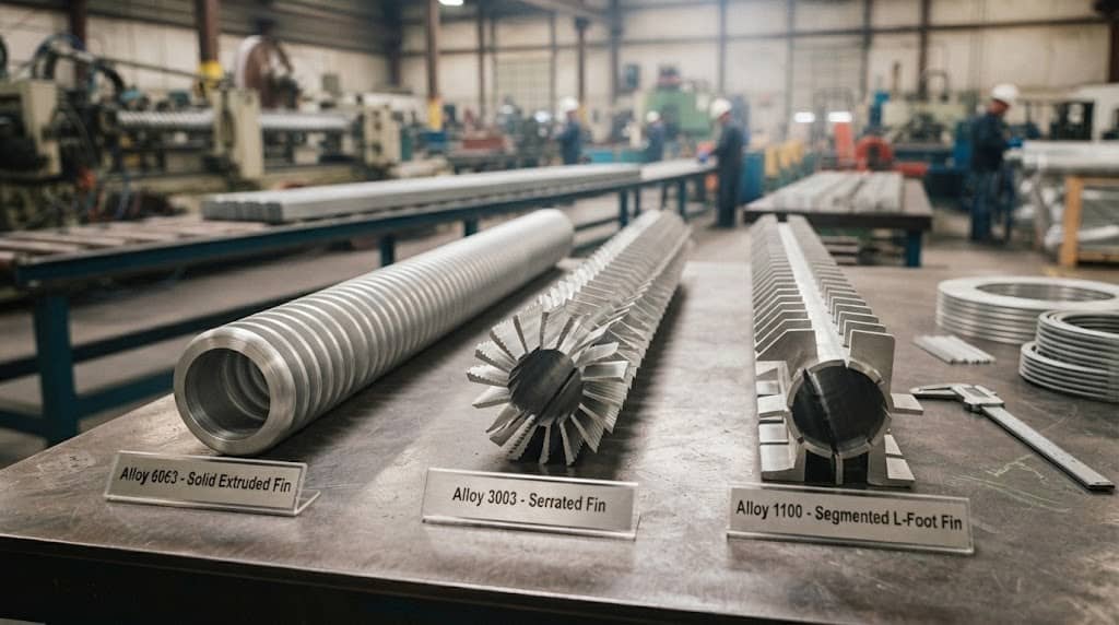
The specification should identify the required fin construction, such as:
- Solid fins
- Serrated fins
- Segmented fins
- Custom fin geometry
For specialized applications, provide a technical drawing showing the fin profile, segment arrangement, and dimensional tolerances. If the heat exchanger requires a particular number of fin segments around the tube, this should also be included in the drawing or RFQ.
Select the Finning and Bonding Configuration
Fin geometry alone does not completely describe an aluminum finned tube. The manufacturer also needs to understand how the fins are attached to the tube.
1. Fin Attachment Method
Depending on the product design and application, the construction may use processes such as extruded, embedded, wrapped, welded, or other customized finning methods. The appropriate method depends on:
- Operating temperature
- Thermal performance
- Mechanical requirements
- Vibration
- Thermal cycling
- Corrosion exposure
- Production volume
- Required dimensional accuracy
For this reason, a procurement specification should identify the required construction when it is already established by the heat exchanger design. If the customer does not have a predetermined process, the manufacturer can recommend an appropriate solution based on the operating conditions.
2. Fin-to-Tube Bonding
The contact between the fin and tube influences the thermal path from the tube to the fin. The quality of this connection can directly affect long-term thermal performance. More information on finned tube bonding and heat transfer can help engineers evaluate different attachment configurations.
- Thermal contact
- Mechanical attachment
- Thermal cycling
- Vibration resistance
- Fin stability
- Long-term operating temperature
A secure fin-to-tube connection is particularly important when the heat exchanger experiences repeated temperature changes or mechanical vibration.
3. Unfinned Tube Ends
The unfinned tube ends should be treated as a separate specification item. Clearly define:
- Length of the unfinned section
- Position of the unfinned section
- Required tube-end condition
- Header or manifold connection requirements
For example, a heat exchanger may require a longer bare tube section at both ends for welding, brazing, expansion, or insertion into a header. This information should be provided before production rather than modified after the tubes have been manufactured.
Add Mechanical, Thermal and Dimensional Requirements
A professional aluminum finned tube specification should define not only dimensions but also the performance and tolerance requirements associated with those dimensions.
1. Thermal Requirements
The RFQ should identify the relevant thermal design targets, such as:
- Required heat transfer capacity
- Fluid inlet temperature
- Fluid outlet temperature
- Air-side temperature
- Fluid flow rate
- Air velocity
- Allowable pressure drop
These parameters should be evaluated together because finned tube heat transfer efficiency depends on the interaction between fin geometry, tube characteristics, airflow, fluid conditions, and manufacturing quality.
2. Mechanical Requirements
Depending on the application, specify:
- Operating pressure
- Design pressure
- Mechanical loading
- Vibration
- Thermal cycling
- Installation requirements
For industrial equipment, the finned tube may be exposed to transportation loads, fan vibration, thermal expansion, and repeated startup and shutdown cycles. These requirements should be considered when selecting the tube wall thickness and fin attachment method.
3. Dimensional Tolerances
Tolerance requirements should be defined for critical dimensions, including:
- Tube OD
- Wall thickness
- Tube length
- Fin height
- Fin thickness
- Fin pitch
- Overall finned diameter
- Unfinned end length
- Straightness
Avoid specifying unnecessarily tight tolerances without a functional reason. Excessively tight tolerances can increase manufacturing complexity and cost without improving heat exchanger performance. For a custom finned tube manufacturer, the best specification is one in which every tolerance is connected to an actual assembly or performance requirement.
Define Material, Corrosion and Quality Requirements
A complete specification also establishes how the finished custom aluminum finned tubes will be verified.
1. Material Certification
If material traceability is required, specify it before placing the order. Depending on the project, documentation may include:
- Material certificate
- Alloy verification
- Chemical composition
- Mechanical properties
- Production batch or lot information
- Traceability documentation
For critical industrial projects, the customer should state whether third-party inspection or specific certification is required.
2. Corrosion Requirements
Aluminum has good corrosion resistance in many environments, but the actual service conditions still need to be considered. The specification should identify exposure to:
- Coastal or marine environments
- Chlorides
- High humidity
- Industrial chemicals
- Condensation
- Dissimilar metals
If aluminum is installed alongside copper, steel, stainless steel, or other metals, the heat exchanger design should also consider galvanic corrosion. The objective is not simply to select a corrosion-resistant alloy, but to ensure that the complete assembly is compatible with the operating environment.
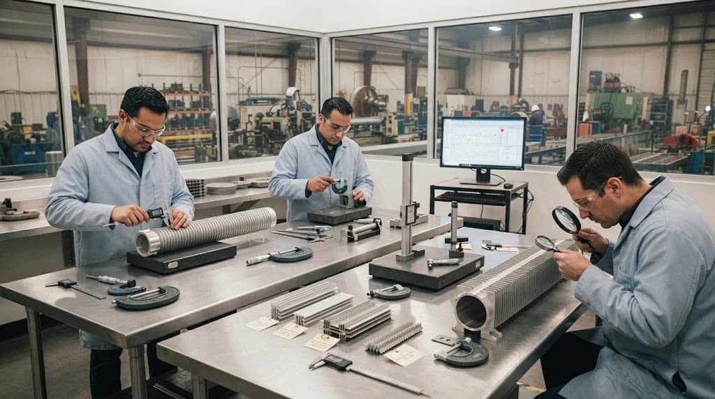
3. Inspection Requirements
The purchase specification should identify the inspections required before shipment. Typical requirements may include:
- Dimensional inspection
- Visual inspection
- Tube integrity testing
- Fin attachment inspection
- Material verification
- Length and straightness inspection
- Packaging inspection
For high-volume or OEM projects, customers may also define sampling plans, inspection frequency, acceptance criteria, and reporting requirements.
Prepare a Complete Aluminum Finned Tube RFQ
After defining the operating conditions, tube, fins, construction, and quality requirements, the information can be organized into a finned tube RFQ specification. A practical RFQ should contain at least the following information:
| Specification | Information to Provide |
| Application | Heat exchanger type and service |
| Heat Duty | Required heating/cooling capacity |
| Tube-Side Fluid | Fluid name and operating conditions |
| Fin-Side Fluid | Air or gas conditions |
| Temperature | Operating and design temperature |
| Pressure | Operating and design pressure |
| Tube Alloy | Required aluminum alloy |
| Tube OD | Nominal outside diameter |
| Wall Thickness | Nominal/minimum thickness |
| Tube Length | Overall and effective length |
| Fin Alloy | Required fin material |
| Fin Type | Solid, serrated, segmented, etc. |
| Fin Height | Nominal dimension and tolerance |
| Fin Thickness | Nominal dimension and tolerance |
| Fin Pitch | Required spacing |
| Fin Density | FPI or other defined value |
| Fin Segments | Number and arrangement |
| Finning Method | Required construction, if specified |
| Unfinned Ends | Length and location |
| Tolerances | Critical dimensional tolerances |
| Quantity | Required production quantity |
| Drawing | 2D/3D drawing or sample |
| Inspection | Testing and certification requirements |
| Packaging | Export and transportation requirements |
Why a Technical Drawing Matters
For a simple standard tube, written specifications may be sufficient. However, a complex custom aluminum finned tube should ideally be accompanied by a 2D engineering drawing or 3D CAD file.
The drawing can define relationships that are difficult to communicate through text alone, including:
- Fin profile
- Tube dimensions
- Fin height
- Fin pitch
- Overall diameter
- Unfinned sections
- Segment geometry
- Tolerances
- End configuration
If the customer has an existing sample, drawing, or heat exchanger core, providing it to the manufacturer can significantly reduce interpretation errors during quotation and production.
Common Specification Mistakes When Ordering Custom Finned Tubes
Even technically experienced buyers can omit important information when preparing an aluminum finned tube RFQ.
Mistake 1: Providing Only Tube OD
A specification such as “19 mm aluminum finned tube” does not define the product sufficiently. The manufacturer still needs to know the tube wall thickness, tube length, fin height, fin pitch, fin thickness, fin type, and end configuration.
Mistake 2: Specifying Fin Density Without a Measurement Convention
“High fin density” is not a precise engineering specification. Always define the actual fin pitch or fins-per-inch value, together with the measurement convention.
Mistake 3: Ignoring Unfinned Tube Ends
The finned section may look correct but still fail during assembly if the bare tube section is too short for the header or connection.
Mistake 4: Choosing Fin Dimensions Without Airflow Information
More fins or taller fins do not automatically produce better heat exchanger performance. Fin geometry must be evaluated together with airflow, pressure drop, available space, heat duty, and cleaning requirements.
Mistake 5: Focusing Only on Unit Price
When comparing quotations from different aluminum finned tube manufacturers, buyers should compare the complete technical specification rather than price per meter alone. Differences in alloy, fin geometry, tolerances, manufacturing method, inspection requirements, and packaging can significantly affect the actual value of the product.
Mistake 6: Ordering Without a Technical Drawing
For complex OEM applications, a drawing provides a common technical reference for the buyer, engineer, and manufacturer. A well-defined drawing can prevent misunderstandings about dimensions that might otherwise lead to rejected components or costly modifications.
FAQs
Q1: How do I specify aluminum fin height and fin pitch?
State the nominal dimension and tolerance. For fin pitch, also identify the measurement convention, such as millimeters between fins or fins per inch.
Q2: What tube diameter and wall thickness should I specify?
The tube OD and wall thickness should be determined according to fluid flow, pressure, heat transfer requirements, mechanical strength, and connection design rather than selected independently.
Q3: What tolerances should be included in an aluminum finned tube specification?
At minimum, consider tolerances for tube OD, wall thickness, length, fin height, fin thickness, fin pitch, overall diameter, straightness, and unfinned end length. Critical tolerances should be linked to the actual assembly requirements.
Q4: What is the difference between fin pitch and fin density?
Fin pitch describes the distance between adjacent fins, while fin density describes how many fins are installed over a defined length. Both describe fin spacing but should be specified using a clearly defined measurement convention.