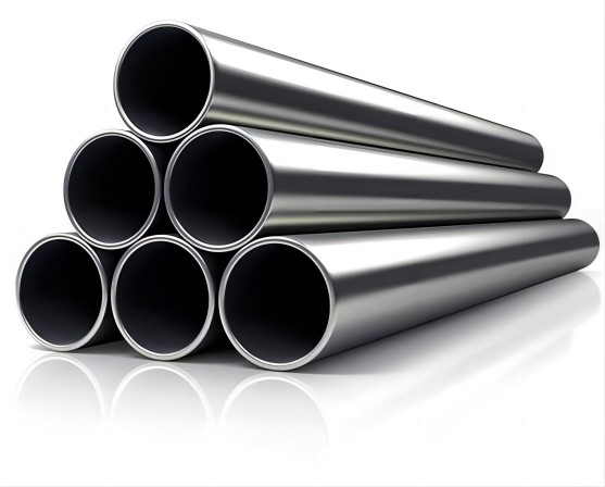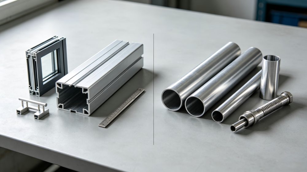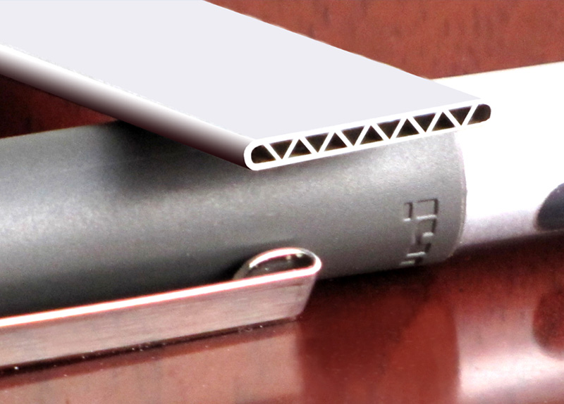
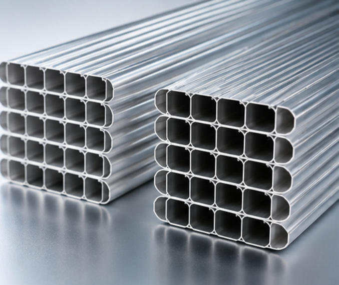
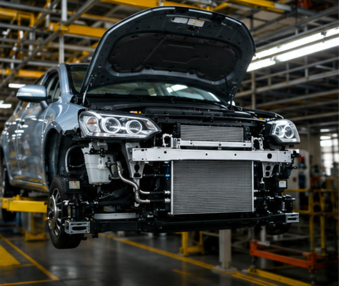
Aluminium micro-channel tubes, also called multi-port extrusion (MPE) tubes, are the preferred solution for modern heat exchangers due to their high heat transfer efficiency, lightweight construction, and excellent corrosion resistance. They are widely used in automotive air conditioning systems, HVAC equipment, heat pumps, refrigeration systems, cooling of EV batteries and industrial heat exchangers.
But choosing the correct aluminium micro-channel tube is more than a size pick. The tube geometry, the alloy composition, the wall thickness, the port configuration, the pressure resistance, the brazing compatibility and the manufacturing quality all have an effect on the efficiency, durability and service life of the final heat exchanger.
This guide will explain the key factors engineers and purchasing managers should evaluate before selecting an aluminium micro-channel tube.
Why Tube Selection Matters in Heat Exchanger Design?
The micro-channel tube is the basic building block of parallel-flow heat exchangers and is the main fluid passageway for phase-change refrigerants or single-phase coolants. The tube controls the fluid dynamics inside and the dissipation of heat outside. Thus, the precise arrangement directly controls several key performance parameters :
- Heat Transfer Efficiency: The internal hydraulic diameter, boundary layer disruption, and surface area to volume ratio determine the rate at which thermal energy is exchanged between the working fluid and the surrounding aluminium fins.
- Refrigerant pressure drop: The number and internal port cross-sectional area have been balanced so that excessive frictional pressure losses do not occur, which may otherwise reduce compressor efficiency and system coefficient of performance (COP).
- Mechanical Strength and Burst Resistance: The tube should withstand high internal pressures of the fluids, cyclic thermal expansion and mechanical vibrations without deforming or bursting.
- Corrosion Resistance: Working in aggressive environments (such as coastal marine atmospheres, high-humidity industrial zones or salted winter roadways) requires superior metallurgical defences against intergranular and pitting corrosion.
- Brazing Performance: Tube exhibits chemical and thermal compatibility with clad layers, fluxes and header plates in Controlled Atmosphere Brazing (CAB) lines to create leak-free, high-integrity joints.
- System weight and material economy: The reduction of raw materials expenditure allows minimising the parasitic weight of a vehicle or equipment by optimising the wall thickness and geometry.
Selecting an inappropriate tube can trigger a chain reaction of downstream failures such as high pressure drop, lower system cooling capacity, micro-leaks with refrigerant or coolant loss, early structural corrosion, brazing joint defects, and increased warranty or production costs. Hence, careful selection of tubes is an essential prerequisite for long-term reliability and market competitiveness.
Step 1: Define Your Application and Operating Environment
Before engaging with any microchannel tube supplier, engineers must establish a clear, comprehensive baseline of the intended application parameters. Different thermal management sectors impose vastly divergent mechanical, chemical, and thermal loads on the heat exchanger tube.
| Application Sector | Typical Operating Requirements & Challenges |
| Automotive Condenser | High operating pressure, excellent high-temperature brazing compatibility, lightweight design, resistance to road vibrations. |
| Automotive Evaporator | Small hydraulic diameter for maximum surface-to-volume ratio, high condensation efficiency, strict cleanliness standards. |
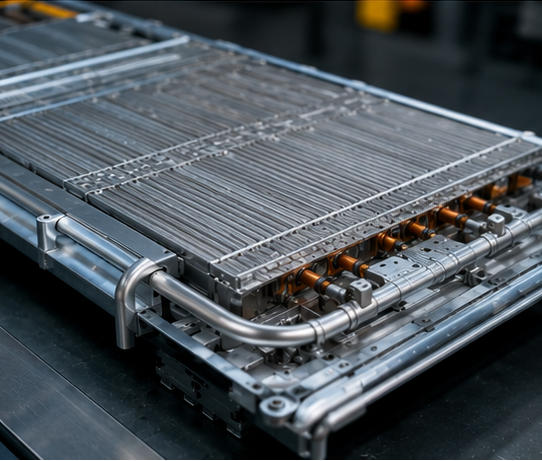
| EV Battery Cooling Plate | Ultra-thin walls, superior coolant compatibility (glycol-water mixtures), exceptional corrosion resistance, high structural integrity. |
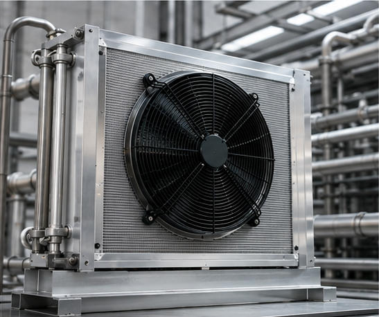
| HVAC Heat Exchanger | High thermal transfer efficiency, resistance to environmental pollutants, long operational lifespan (10–15+ years). |
| Heat Pump Systems | High operating pressure (especially with advanced eco-friendly refrigerants), cyclic thermal fatigue, severe freeze-thaw resilience. |
| Commercial Refrigeration | High thermal conductivity, durability under continuous heavy-duty cycling, resistance to aggressive defrost chemicals. |
To improve the selection process, engineers must specify the following operational parameters clearly:
- Working Fluid: Identify if the system employs HFCs (e.g., R134a), HFOs (e.g., R1234yf), natural refrigerants (e.g., R290 propane, CO₂ R744), or liquid coolants (water-glycol).
- Operating Pressure: Identify nominal working pressures and peak transient pressures, including maximum allowable working pressure (MAWP)
- Operating Temperature Range: Take into account cryogenic start-up conditions as well as high-temperature stagnation peaks.
- Required Thermal capacity: Measure the load of heat rejection or absorption the core has to provide.
- Expected Life Cycle: List hours of operation, severity of environment exposure.
Step 2: Select the Appropriate Aluminum Alloy
The material selection is the key decision to determine mechanical strength, formability, corrosion resistance, and brazing capability of aluminium MPE tube. The 3xxx and 4xxx series are the main aluminium alloys for extrusion and for brazing, often with special cladding layers or surface treatments.
Comparative Overview of Aluminum Alloys
- 3003 Alloy: The all-around thermal application material. It is highly resistant to corrosion, easy to form and has reliable mechanical strength. For this reason, it is the industry standard for stationary HVAC and commercial refrigeration systems.
- 3102 Alloy: Special modification with improved brazability and uniformity in extrusion. It is widely specified for automotive condensers and high-pressure OEM applications where clean extrusion profiles and tight metallurgical controls are mandatory.
- 4343 Clad Material: Cladding layer of aluminum-silicon (Al-Si) bonded to core alloy. This cladding acts as an inbuilt braze filler material during Controlled Atmosphere Brazing (CAB), thus eliminating the need for an external filler wire.
- 4045 Clad Material: Higher silicon content in the brazing layer providing a lower melting point range. This is often applied in high-performance heat exchangers where fast, defect-free fillet formation is required under tight thermal cycles.
- 7072 Zinc Coating: An external coating which protects against corrosion by sacrificial means. The zinc-rich outer layer corrodes preferentially over the structural core alloy, protecting the tube from pitting corrosion in coastal environments or road-salt-exposed automotive applications.
Strategic Alloy Recommendations
For standard HVAC and refrigeration applications, 3003 alloy provides the optimal balance of cost, formability, and baseline corrosion resistance. For demanding automotive condensers and high-pressure OEM systems, 3102 alloy combined with specialized cladding or zinc-arc spraying ensures superior fatigue strength and joint integrity.
Step 3: Optimize Tube Dimensions and Cross-Sectional Geometry
3003 alloy is the best balance of cost, formability and baseline corrosion resistance for standard HVAC and refrigeration applications. 3102 alloy with special cladding or zinc-arc spraying is the ideal choice for automotive condensers and high-pressure OEM applications where superior fatigue strength and joint integrity are required.
Key Dimensional Parameters
- Tube Width: Common commercial widths are 10mm, 12mm, 16mm, 20mm, 25mm. Wider tubes allow for more area for the fin to be attached to, and better internal flow distribution. Narrower tubes are preferred for compact headers, where space is at a premium.
- Thickness (Height) of Tube: Generally available in 1.0mm, 1.2mm, 1.5mm, 2.0mm and 3.0mm. The height influences the refrigerant distribution inside the heat exchanger, the flow area of the cross section and the mechanical out-of-plane bending strength.
- Wall Thickness: Normal wall thicknesses are 0.20 mm, 0.25 mm, 0.30 mm, 0.35 mm and 0.40 mm. Thicker walls allow a greater margin of safety for burst pressure, but introduce a thermal resistance which can marginally decrease the overall heat transfer efficiency. The engineers have to optimise the wall thickness with respect to the constraints given by maximum operating pressure.
- Tube Length: Extruded tubes are generally supplied in continuous coils, but cut-to-length straight sections can be supplied to the exact core dimensions required by the heat exchanger design.
Step 4: Configure Internal Port Design and Channel Density
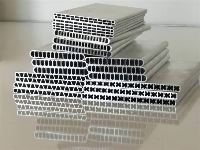
The number and geometry of internal channels (ports) within an aluminum multi-port extrusion tube directly govern internal fluid dynamics, heat transfer coefficients, and refrigerant charge volume.
Port Configuration Breakdown
- 7 Ports: Suited for compact, low-capacity heat exchangers or specialized auxiliary cooling loops.
- 11 Ports: Frequently deployed in automotive evaporators where high evaporation heat transfer coefficients are required within strict spatial limits.
- 16 Ports: The industry standard for automotive condensers, offering a balanced compromise between internal surface area and fluid pressure drop.
- 20 Ports: Widely utilized in stationary HVAC systems to maximize internal turbulence and convective heat transfer.
- 30 to 40 Ports: Engineered for large commercial heat exchangers and high-capacity industrial chillers requiring extreme thermal performance.
The Trade-Offs of High Port Counts
Increasing the number of internal ports yields significant performance benefits, including higher surface area, better heat transfer, and lower refrigerant charge. However, increasing port density shrinks individual channel hydraulic diameters. Excessively small channels drastically escalate fluid pressure drop, demand higher pumping power, and exponentially increase the manufacturing complexity and tooling precision required by the microchannel tube supplier.
Step 5: Evaluate Pressure Requirements and Burst Strength
Operating pressures vary dramatically depending on the working fluid and thermodynamic cycle employed by the thermal system. Modern eco-friendly refrigerants and high-efficiency systems operate under severe pressures that demand rigorous mechanical validation.
Refrigerant Pressure Profiles
- R134a and R1234yf: For most automotive applications, the medium pressure ratings, typical extrusion profiles and wall thicknesses are adequate.
- R410A and R32: These are high operating pressure refrigerants which require tighter dimensional control, optimised port webs and robust wall thicknesses to prevent creep or fatigue failure.
- CO₂ (R744): Operates at very high transcritical pressures (often above 100 bar during operation). The CO2 systems need heavy-duty, thick-walled micro-channel tubes engineered from special high-strength alloys with validation by stringent burst-pressure testing.
To ensure the structural safety of the tube and the system design, engineers need to demand that suppliers provide certified burst pressure test reports and cyclic fatigue performance data with the tube selected, oversizing maximum allowable working pressure thresholds by a safety factor of 3x to 5x.
Step 6: Implement Effective Corrosion Resistance Strategies
Aluminium micro-channel tubes are protected by a thin passive layer of aluminium oxide (Al2O3). However, under severe service conditions, this natural barrier can be quickly compromised, resulting in localised pitting, intergranular attack and premature tube perforation.
Environmental Stress Factors
- Coastal Regions: High airborne chloride and sodium concentrations accelerate electrochemical corrosion.
- High Humidity and Industrial Zones: Acidic precipitation and airborne industrial pollutants attack exposed aluminum surfaces.
- Road Salt Exposure: Winter de-icing chemicals create aggressive electrolyte solutions that attack automotive condensers and EV cooling plates.
Corrosion Mitigation Engineering
To ensure long-term durability, several advanced protection methodologies must be evaluated:
Zn-Coated Tubes: Applying a controlled zinc layer via thermal spraying or electroplating provides active cathodic protection.
7072 Sacrificial Cladding: Bonding a metallurgically distinct 7072 alloy layer to the exterior ensures that corrosion sacrifices the outer cladding rather than penetrating the structural core.
Surface Passivation and Conversion Coatings: Chemical treatments that thicken and stabilize the protective oxide film.
Optimized Drainage Design: Ensuring structural layout prevents moisture pooling on the heat exchanger face.
For outdoor and vehicular applications, corrosion resistance is frequently more critical than mechanical strength, as premature pitting leads instantly to catastrophic system depressurization.
Step 7: Ensure Compatibility with Controlled Atmosphere Brazing (CAB)
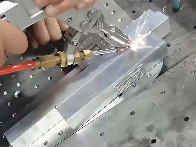
Most aluminium heat exchangers are manufactured by means of Controlled Atmosphere Brazing (CAB) in continuous nitrogen atmosphere furnaces. The success of the brazing operation is totally dependent on the metallurgical compatibility between the micro-channel tube, the header components, the fins and the applied brazing fluxes.
Brazing Compatibility Key Considerations
- CAB Furnace Temperature Profile: The melting point of the brazing filler (clad layer) needs to be in the same temperature zone as the peak temperature of the furnace (generally between 595°C and 605°C) but not melting the structural core alloy.
- Cladding Thickness and Uniformity: Inconsistent clad thickness can cause insufficient fillet formation or excessive erosion of the tube wall.
- Flux Coating Quality: Non-corrosive fluxes such as caesium or potassium fluoroaluminate fluxes should wet out the aluminium surface uniformly to dissolve surface oxides.
- Design of tube-to-header joint: The depth of insertion, the tolerances on the slot and the geometry of the collar should be such that thermal expansion on heating can be accommodated while capillary action is maintained for the flow of filler metal.
Poor brazing compatibility always leads to weak structural joints, internal and external leakage, and a very low fatigue life.
Step 8: Verify Manufacturing Quality and Tolerances
Micro-channel extrusion is a precision manufacturing process. Minor differences in extrusion tooling, press speed, or cooling rates can cause serious structural defects that can destroy the integrity of the heat exchanger core.
Parameters for Quality Check
- Dimensional Accuracy: Check close tolerances for width tolerance, height tolerance, wall thickness tolerance, and straightness. But even a little bow or camber can throw the tubes out of alignment in automated core assembly.
- Surface Quality: Inspect closely for scratches, burrs, surface oxidation, and contamination with organic lubricant, all of which will prevent braze wetting.
- Internal Port Quality: Consistent port geometry, no collapsed channels, smooth internal surfaces to avoid flow restriction and localised stress concentrations.
- Mechanical Testing: Mandate comprehensive quality assurance reports covering tensile strength, burst pressure, hardness, and metallographic grain structure inspection.
Step 9: Evaluate Supplier Manufacturing Capabilities
Selecting the right microchannel tube supplier is just as important as specifying the correct tube geometry. A world-class supplier must offer far more than basic extrusion services; they should act as a collaborative engineering partner throughout the product development lifecycle.
Essential Supplier Capabilities
- Advanced Extrusion Lines: State-of-the-art hydraulic presses equipped with real-time temperature and pressure monitoring systems.
- Precision Tooling Expertise: In-house die design and wire-EDM manufacturing capabilities to rapidly prototype custom port geometries.
- Metallurgical Support: Deep expertise in alloy development, cladding metallurgy, and microstructural analysis.
- CAB Brazing Technical Support: Ability to provide guidance on flux selection, temperature profiles, and joint design.
- Production Capacity and Scalability: Stable, high-volume output capable of meeting global supply chain demands without compromising lead times.
- Comprehensive Quality Assurance: Rigorous internal testing laboratories certified to automotive and industrial quality standards (such as IATF 16949 and ISO 9001).
Common Selection Mistakes to Avoid
Avoiding common engineering pitfalls during the specification phase prevents costly redesigns, manufacturing delays, and field failures.
- Choosing the Lowest-Cost Tube: Focusing exclusively on raw material price often compromises alloy purity and dimensional tolerances, resulting in reduced durability and higher lifecycle costs.
- Ignoring Corrosion Protection: Neglecting environmental exposure factors leads to premature failure in harsh environments, particularly in coastal or salted-road applications.
- Selecting Too Many Ports: Over-specifying port density for a given fluid flow rate causes excessive pressure drop, inflating system pumping energy requirements.
- Using Insufficient Wall Thickness: Thinning walls to save weight without verifying pressure safety margins risks burst failure under high pressure.
- Overlooking Brazing Compatibility: Failing to coordinate cladding alloys with furnace parameters results in joint leakage and reduced reliability.
- Focusing Only on Heat Transfer: Ignoring structural, hydraulic, and mechanical constraints leads to imbalanced system performance.
Frequently Asked Questions
What is the best aluminum alloy for micro-channel tubes?
3003 aluminium is an excellent combination of corrosion resistance and formability for most HVAC and refrigeration systems. The choice of material for automotive heat exchangers that need superior brazing performance is frequently 3102 aluminium, particularly when combined with clad brazing layers.
How do I choose the number of ports?
The optimal port count depends on the desired balance between heat transfer efficiency and pressure drop. More ports generally improve heat transfer by increasing the internal surface area but also create smaller flow passages that can raise pressure loss.
What wall thickness is recommended?
Wall thickness is determined by the operating pressure and structural requirements. Typical values range from 0.20 mm to 0.40 mm. High-pressure systems or applications using CO₂ refrigerants generally require thicker walls.
Can aluminum micro-channel tubes be customized?
Yes. Most manufacturers can customize the alloy, width, height, wall thickness, number of ports, tube length, clad layer, and surface treatment to meet specific heat exchanger designs and performance targets.
Which industries use aluminum micro-channel tubes?
These tubes are widely used in automotive air conditioning, commercial HVAC, heat pumps, refrigeration equipment, electric vehicle battery cooling, industrial cooling systems, and increasingly in liquid cooling solutions for high-performance electronics and data centers.