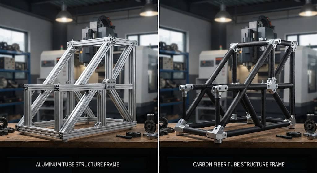
When designing a lightweight tubular structure, choosing between an aluminum tube and a carbon fiber tube requires more than comparing material weight or tensile strength. Tube diameter, wall thickness, load direction, unsupported length, joint design, manufacturing process, and thermal requirements can all affect the final design.
This guide focuses specifically on aluminum tube vs carbon fiber tube selection for structural applications, explaining how engineers can evaluate tube geometry, bending, buckling, connections, manufacturing, and application requirements before selecting a tube construction.
Why Tube Geometry Matters in Aluminum vs Carbon Fiber Tube Selection?
A direct aluminum tubing vs carbon fiber tubing comparison can be misleading because tube geometry strongly influences structural performance. For bending applications, a simplified relationship is:
Bending stiffness ≈ E × I
where E is the elastic modulus and I is the second moment of area.
Therefore, an engineer selecting an aluminum tube or carbon fiber tube should evaluate:
- Outside diameter
- Wall thickness
- Cross-sectional shape
- Tube length
- Unsupported span
- Required stiffness
- Allowable deflection
- Available installation space
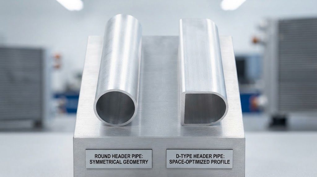
A larger-diameter tube can substantially increase bending stiffness without simply increasing material thickness. This makes tube geometry optimization an important part of lightweight structural design.
The key question is therefore not simply which material is stronger, but which tube geometry and material combination provides the required structural performance within the available mass and dimensional limits.
Design the Load Case Before Choosing the Tube
The appropriate carbon fiber tube vs aluminum tube solution depends heavily on the dominant load.
| Structural Load | Primary Design Consideration |
| Bending | Stiffness and allowable deflection |
| Axial tension | Cross-sectional area and tensile capacity |
| Compression | Global and local buckling |
| Torsion | Tube geometry and torsional stiffness |
| Impact | Local deformation and damage tolerance |
| Vibration | Stiffness, mass distribution and natural frequency |
| Combined loading | Interaction between multiple load cases |
For example, a long tube under compression may be governed by buckling rather than the material’s nominal tensile strength. A simplified Euler buckling relationship is:
Critical buckling load ∝ EI/L²
where L represents unsupported length. This means that tube length, diameter, cross-sectional geometry and stiffness should be considered together when evaluating lightweight structural tubing.
Aluminum Tube vs Carbon Fiber Tube for Bending and Buckling
1. Bending stiffness
For a tubular structure, placing material farther from the neutral axis can increase resistance to bending. Engineers can therefore adjust:
- Tube diameter
- Wall thickness
- Cross-sectional profile
- Material stiffness
- Total structural mass
A carbon fiber tube can also be engineered with different fiber orientations and laminate configurations to produce directional stiffness. Aluminum tubing generally provides more uniform material behavior and can be specified through established tube dimensions, alloy and temper. Therefore, the comparison should be made at the tube-design level, rather than by comparing material modulus alone.
2. Global buckling
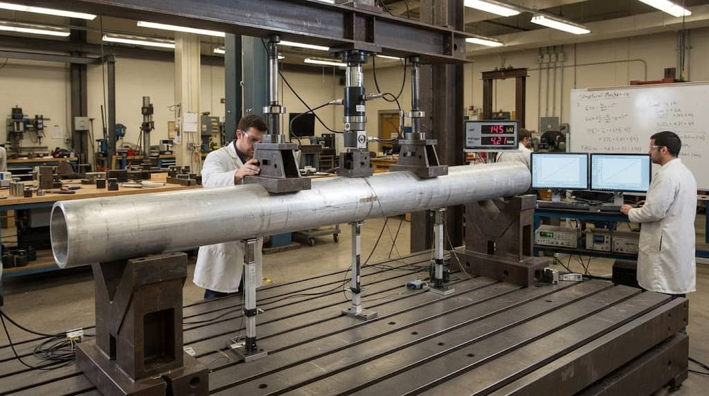
Long aluminum tubes and carbon fiber tubes used as compression members should be evaluated for:
- Unsupported length
- End conditions
- Tube diameter
- Wall thickness
- Structural stiffness
- Initial geometric imperfections
Increasing tube diameter can sometimes improve resistance to bending and buckling without proportionally increasing wall thickness.
3. Local wall buckling
Thin-wall tubing introduces another consideration: local wall instability.
Particular attention is required around:
- Bolted connections
- Clamps
- Brackets
- Inserts
- Load-bearing contact points
A lightweight tube can have adequate overall strength while still requiring reinforcement around concentrated load areas.
Connection Design: A Key Difference Between Aluminum and Carbon Fiber Tubes
The connection method can influence the selection of aluminum tube vs carbon fiber tube from the beginning of the design process.
1. Aluminum tube joining
Aluminum tubing can be integrated using:
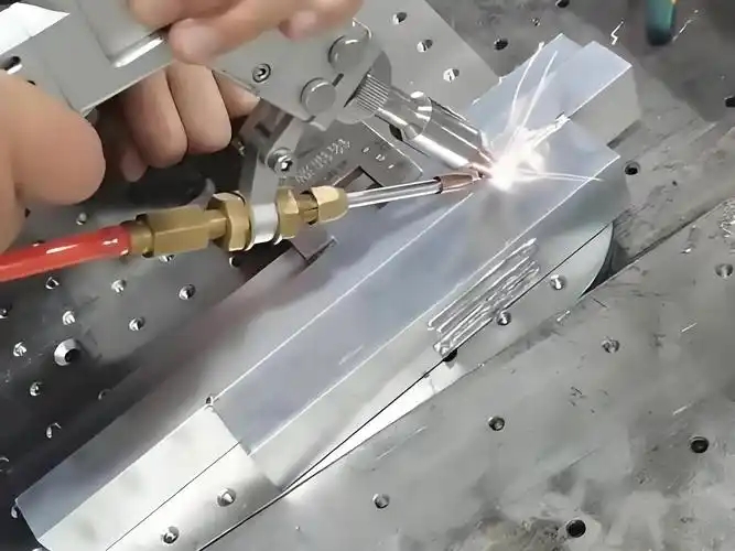
- Welding
- Bolting
- Clamping
- Mechanical fittings
- Machined connectors
- Adhesive bonding
Welding can simplify metal-frame fabrication, while machining and drilling provide flexibility for assembly and modification. CHAL supplies extruded and drawn aluminum tubes in different dimensions and configurations, allowing tube selection to be matched to the required structural and manufacturing conditions.
2. Carbon fiber tube joining
Carbon fiber tubing often requires more specialized connection strategies, especially when concentrated loads are transferred into the composite section.
Typical approaches include:
- Adhesive bonding
- Bonded inserts
- Mechanical fasteners
- Clamps
- Hybrid metal-composite fittings
The connection should be evaluated together with the tube because drilling or applying concentrated clamping forces can influence local composite behavior.
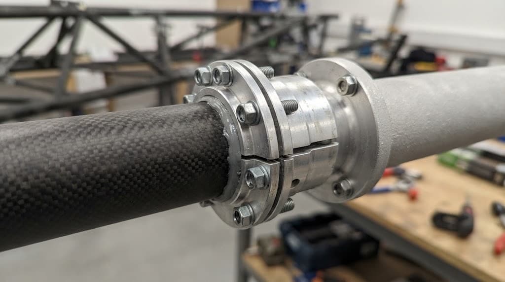
3. Joining carbon fiber and aluminum tubes
A hybrid aluminum-carbon fiber connection introduces additional design considerations:
- Electrical isolation
- Galvanic corrosion
- Adhesive compatibility
- Differential thermal expansion
- Load transfer
- Insert design
Therefore, carbon fiber tube and aluminum tube hybrid structures should be designed as complete assemblies rather than treating the two materials independently.
Manufacturing Considerations for Aluminum and Carbon Fiber Tubes
The manufacturing route can affect tube geometry, tolerances, connections and production economics.
1. Aluminum tube manufacturing
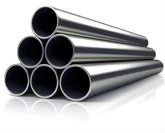
Aluminum tubing can be produced through extrusion, drawing and other secondary processes. Extrusion is useful for defined cross-sectional profiles, while drawing can provide tighter dimensional control and specialized tube configurations.
For an aluminum structural tube, engineers should consider:
- Standard or custom profile availability
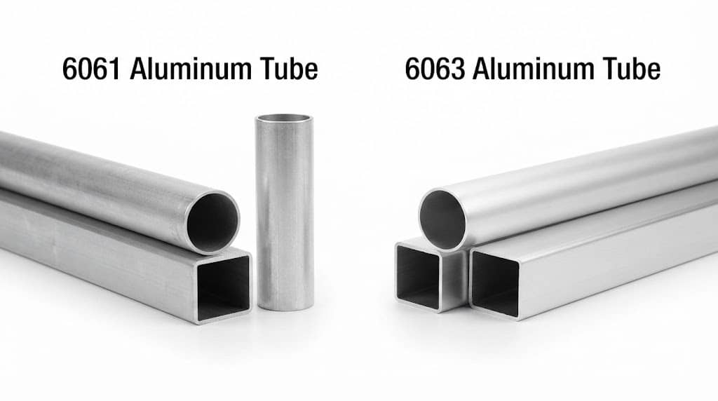
- Alloy and temper
- Wall thickness
- Dimensional tolerance
- Bending requirements
- Machining
- Joining method
- Production volume
CHAL’s product portfolio includes extruded aluminum tube, seamless aluminum tube and drawn aluminum tube, allowing different manufacturing routes to be matched with application requirements.
2. Carbon fiber tube manufacturing
Carbon fiber tube design is closely connected to its manufacturing process. Important variables include:
- Fiber orientation
- Layup structure
- Number of plies
- Resin system
- Mandrel or tooling
- Curing process
- End fittings
- Local reinforcement
This enables directional structural optimization but also means the tube design and manufacturing specification need to be developed together.
Thermal and Electrical Requirements
Structural performance is not always the only reason to select a tube material.
1. Thermal management
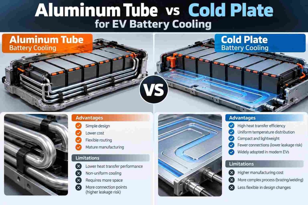
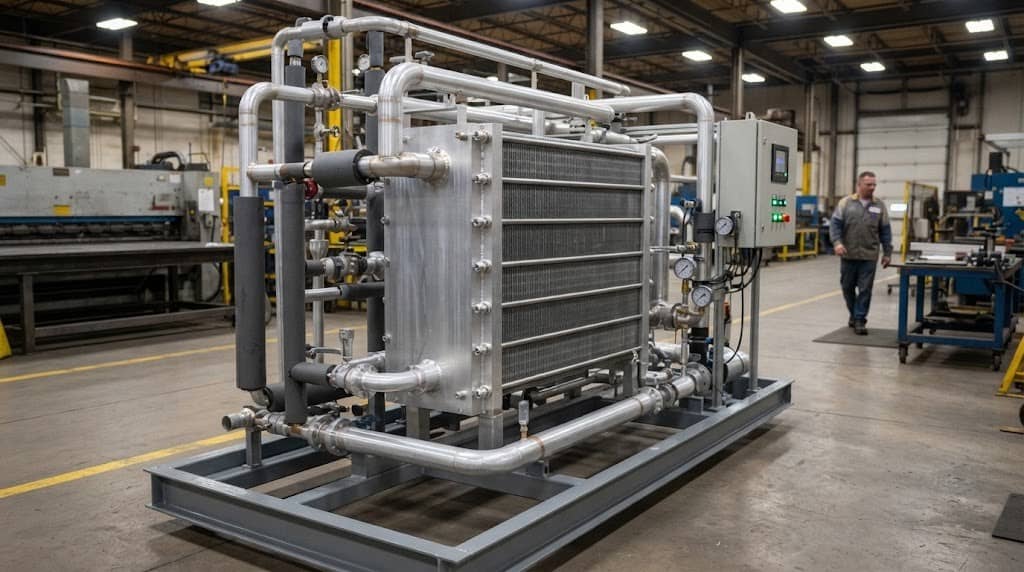
For applications where the tube also needs to transfer heat, aluminum tubing can provide an important functional advantage. Aluminum tubes are widely used in:
- Heat exchangers
- Automotive thermal management
- HVAC/R systems
- Radiators
- Condensers
- Refrigeration systems
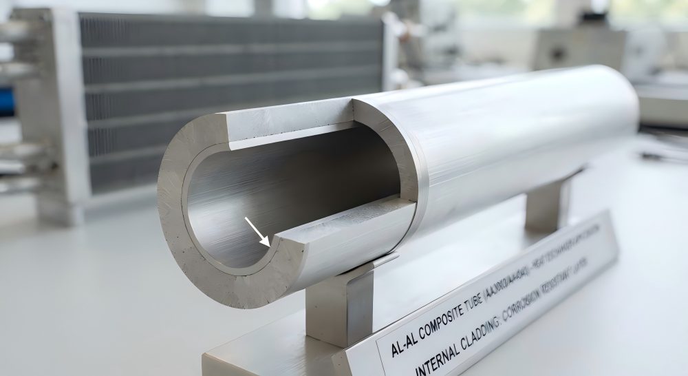
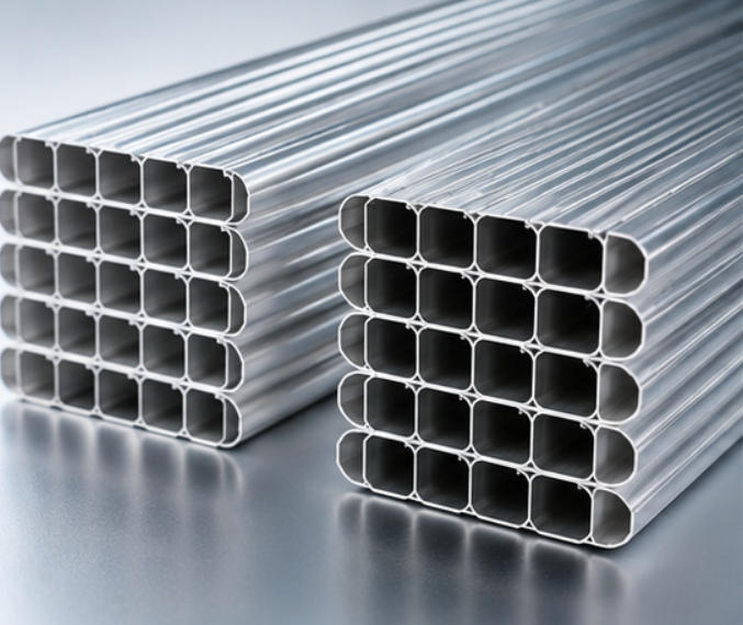
CHAL’s product range includes micro-channel aluminum tubes, drawn aluminum tubes and other heat-transfer tube configurations. This creates a significant difference between a structural carbon fiber tube and an aluminum tube that also functions as part of a thermal system.
2. Electrical behavior
Electrical conductivity can also influence tube selection. Aluminum is electrically conductive, while composite structures can be used where electrical isolation is required. The final choice depends on whether the tube needs to function as part of an electrical, thermal or structural system.
Aluminum Tube vs Carbon Fiber Tube: Application Fit
Instead of asking which tube is universally better, engineers should match the construction to the application’s actual requirements.
| Design Requirement | Primary Evaluation |
| Low structural mass | Mass allocation and geometry |
| High bending stiffness | E × I and section geometry |
| Long compression member | Buckling resistance |
| Concentrated joint loads | Load-transfer design |
| Welded structure | Joining process |
| Directional stiffness | Fiber orientation |
| Heat-transfer function | Thermal conductivity and tube design |
| Field modification | Machining and joining |
| High production volume | Manufacturing scalability |
| Hybrid construction | Interface and isolation design |
This approach makes aluminum tube vs carbon fiber tube selection more useful for engineering and procurement decisions than a simple material advantages-and-disadvantages list.
How to Choose Between an Aluminum Tube and Carbon Fiber Tube?
A practical aluminum tube vs carbon fiber tube selection process can follow these steps:
1. Define the primary load: Identify whether the tube primarily experiences bending, compression, tension, torsion, impact or combined loading.
2. Establish tube geometry: Define diameter, wall thickness, length, cross-sectional shape and available installation space.
3. Set structural limits: Determine allowable deflection, buckling load, vibration requirements and target mass.
4. Define the connection method: Decide whether the assembly requires welding, bolting, clamping, adhesive bonding or inserts.
5. Evaluate manufacturing requirements: Consider tolerances, tooling, machining, forming, production quantity and customization.
6. Check environmental requirements: Evaluate temperature, corrosion, electrical isolation and heat-transfer requirements where applicable.
7. Compare complete tube systems: Finally, compare the tube, joints, fittings, manufacturing process and lifecycle requirements together rather than selecting the material in isolation.
Aluminum Tube vs Carbon Fiber Tube: Engineering Decision Matrix
| Engineering Question | What to Evaluate |
| Is bending deflection critical? | E × I and tube geometry |
| Is the tube very long? | Global buckling |
| Is the wall very thin? | Local buckling and deformation |
| Are concentrated loads present? | Joint and load-transfer design |
| Is welding required? | Fabrication and assembly route |
| Is directional stiffness required? | Fiber orientation and laminate design |
| Is heat transfer required? | Thermal properties and tube configuration |
| Is field modification expected? | Machining and joining options |
| Is high-volume production required? | Tooling and process scalability |
| Are aluminum-composite joints required? | Isolation and interface design |
When Does a Hybrid Aluminum-Carbon Fiber Tube Make Sense?
Hybrid structures can combine an aluminum section for connections or thermal management with carbon fiber where directional stiffness or weight reduction is important. For example, a composite section may be used for a lightweight structural member, while aluminum components provide mounting interfaces, mechanical fittings or thermally conductive sections.
However, hybrid construction introduces additional considerations, including:
- Joint stiffness
- Load transfer
- Thermal expansion
- Galvanic isolation
- Adhesive performance
- Inspection and repair
The interface therefore needs to be designed as part of the overall aluminum and carbon fiber tube system.
FAQ: Aluminum Tube vs Carbon Fiber Tube
Q1: Is an aluminum tube or carbon fiber tube better for bending?
A1: Neither is universally better. Bending performance depends on material stiffness, tube diameter, wall thickness, section geometry, span and allowable deflection.
Q2: How does tube diameter affect aluminum and carbon fiber tube performance?
A2: Increasing tube diameter can significantly increase the second moment of area and therefore bending stiffness. Tube geometry should be evaluated together with wall thickness and material properties.
Q3: Can carbon fiber tubes replace aluminum tubes?
A3: Carbon fiber tubes can replace aluminum tubes in some lightweight structural designs, but suitability depends on load cases, joints, manufacturing requirements, thermal performance and lifecycle requirements.
Q4: Can aluminum and carbon fiber tubes be joined?
A4: Yes. Mechanical fasteners, adhesive bonding, inserts and hybrid fittings can be used. Engineers should also evaluate galvanic isolation and load transfer at the material interface.
Q5: Which is easier to machine and modify?
A5: Aluminum tubes generally offer straightforward machining, drilling, cutting and joining options. Carbon fiber tubes require more specialized processing and local reinforcement may be necessary around machined areas.